PCIe to M.2 adapter for solid-state drive
2026-09-22 18:00:00 | pcba-mkr
PCIE to M.2 adapter with X1, X4, X16 split for 4 disks
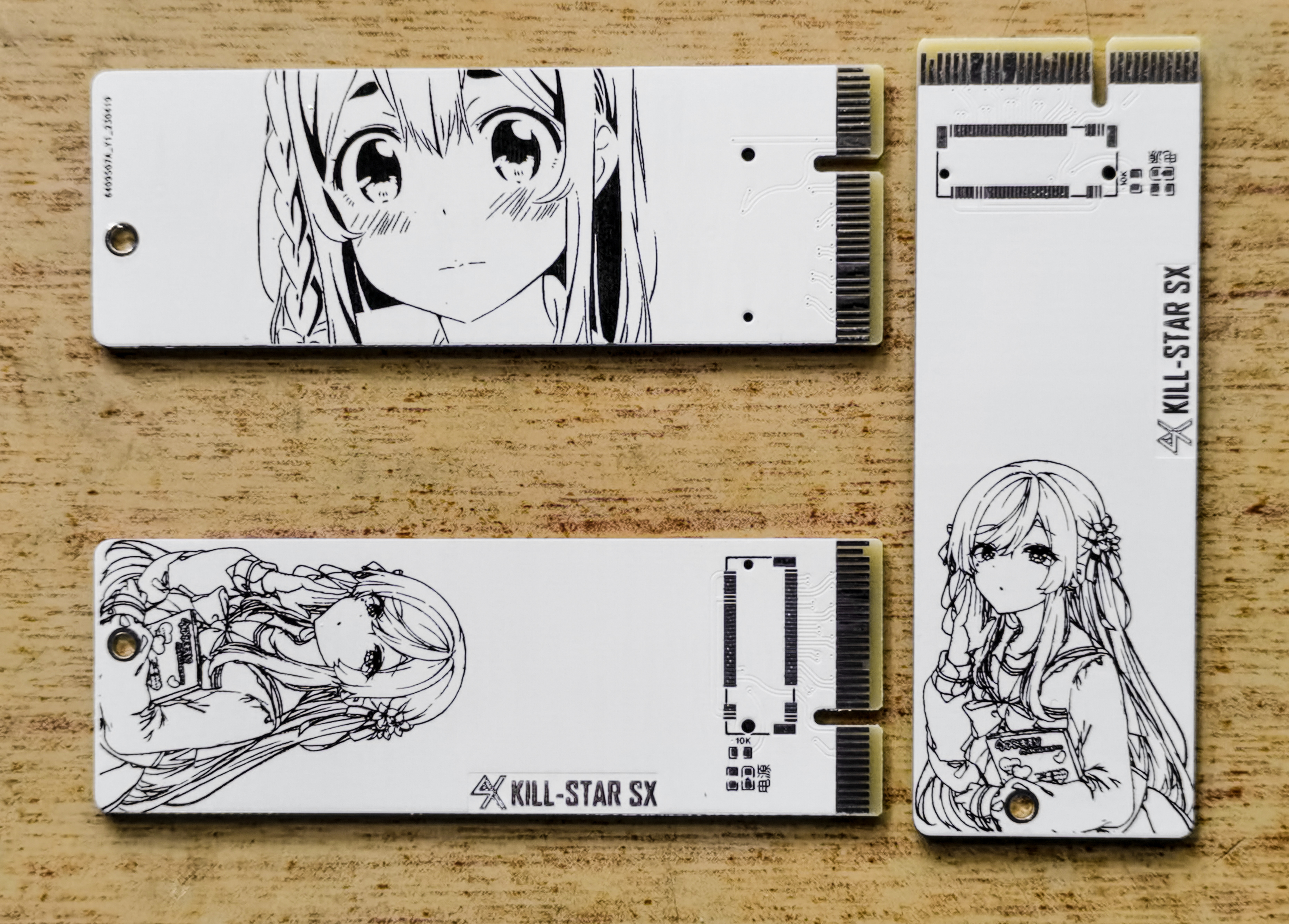
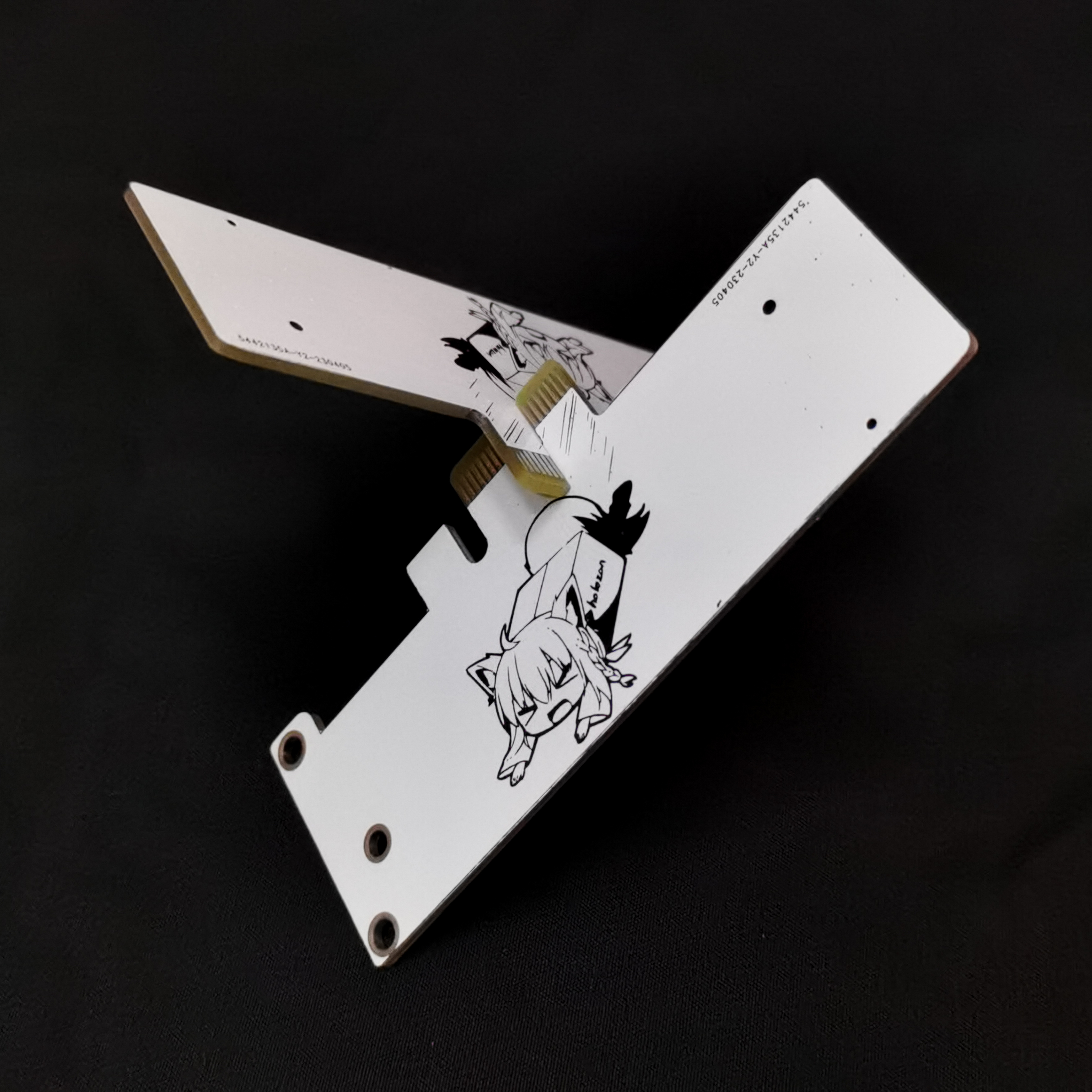
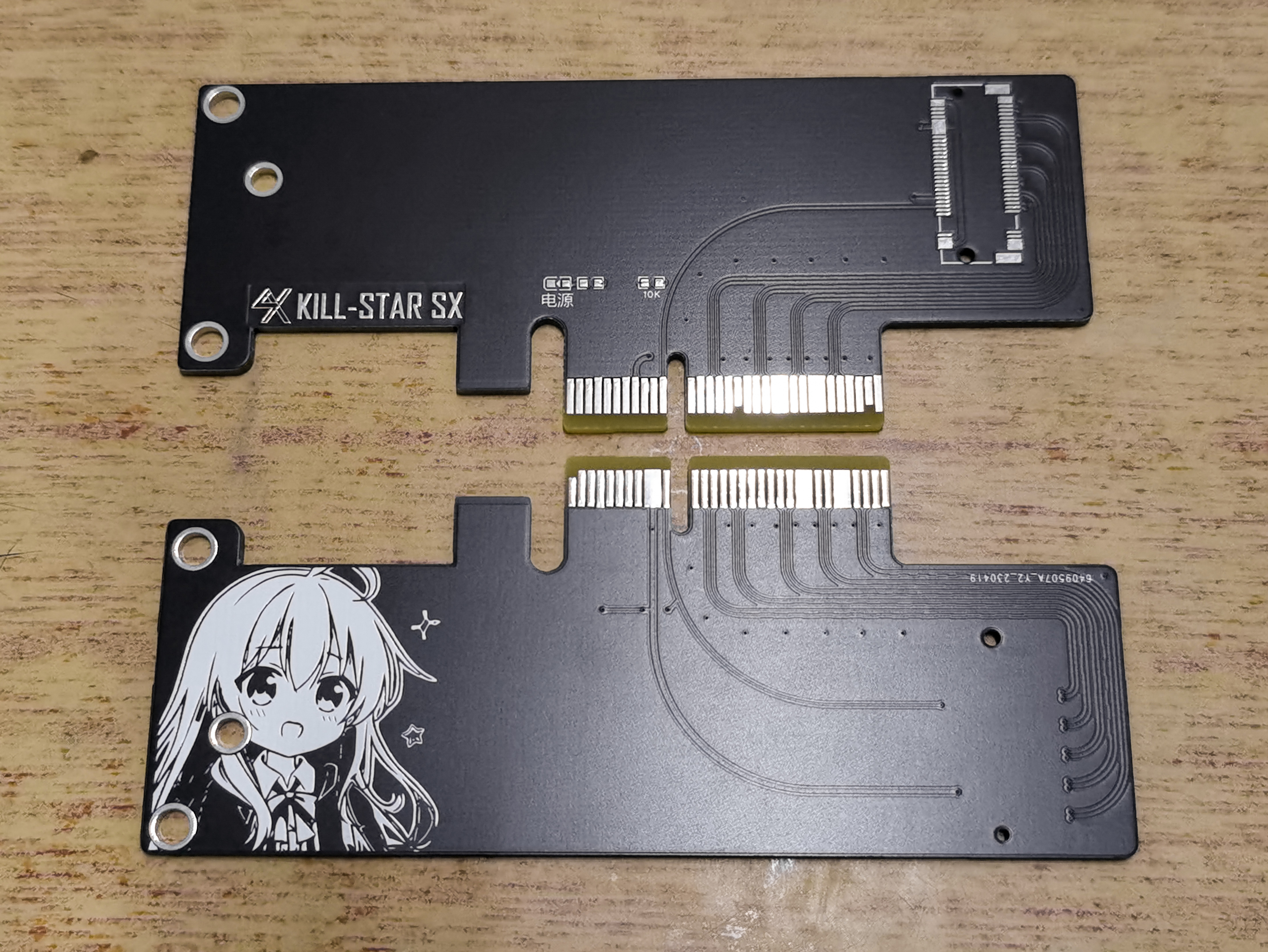
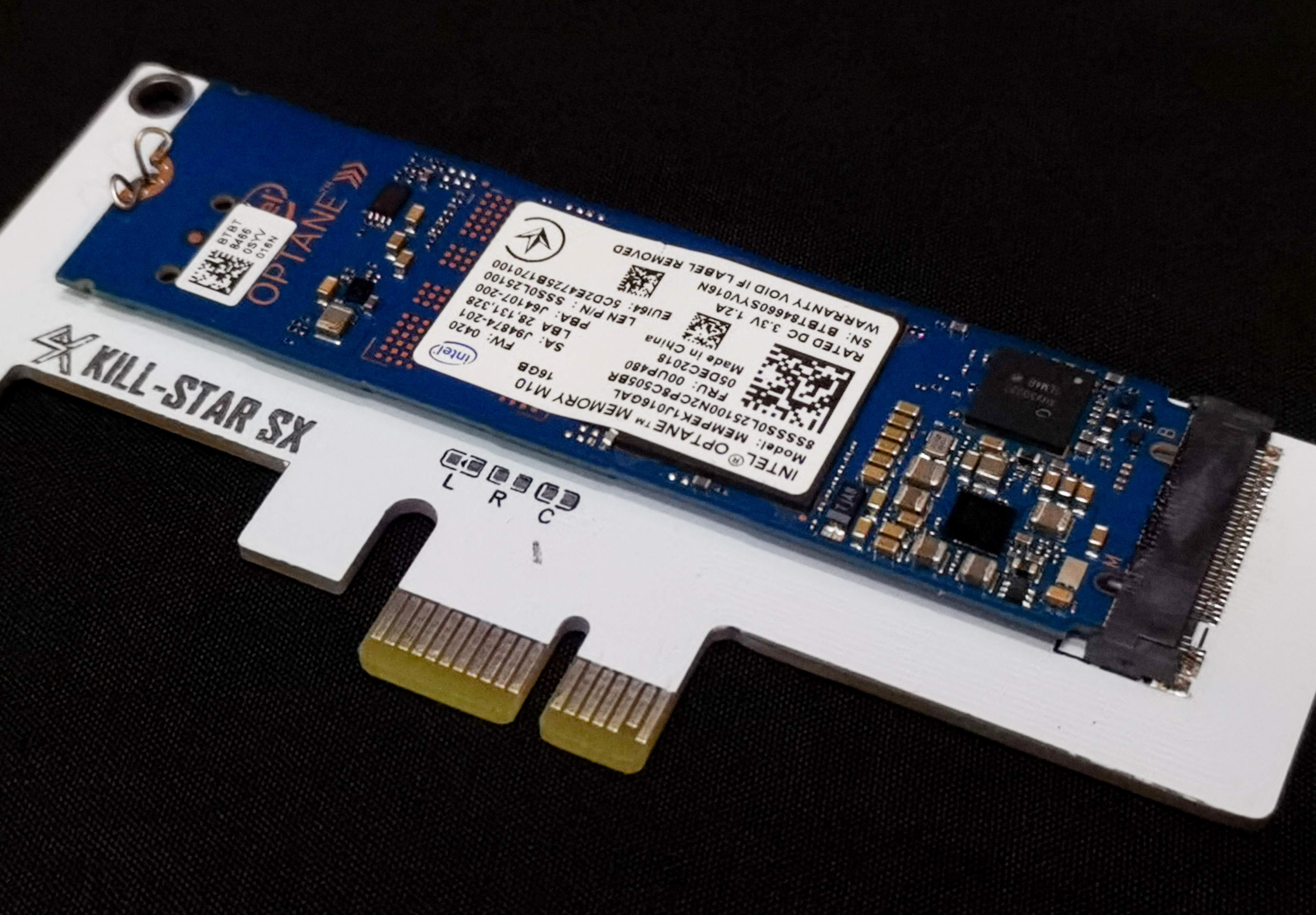
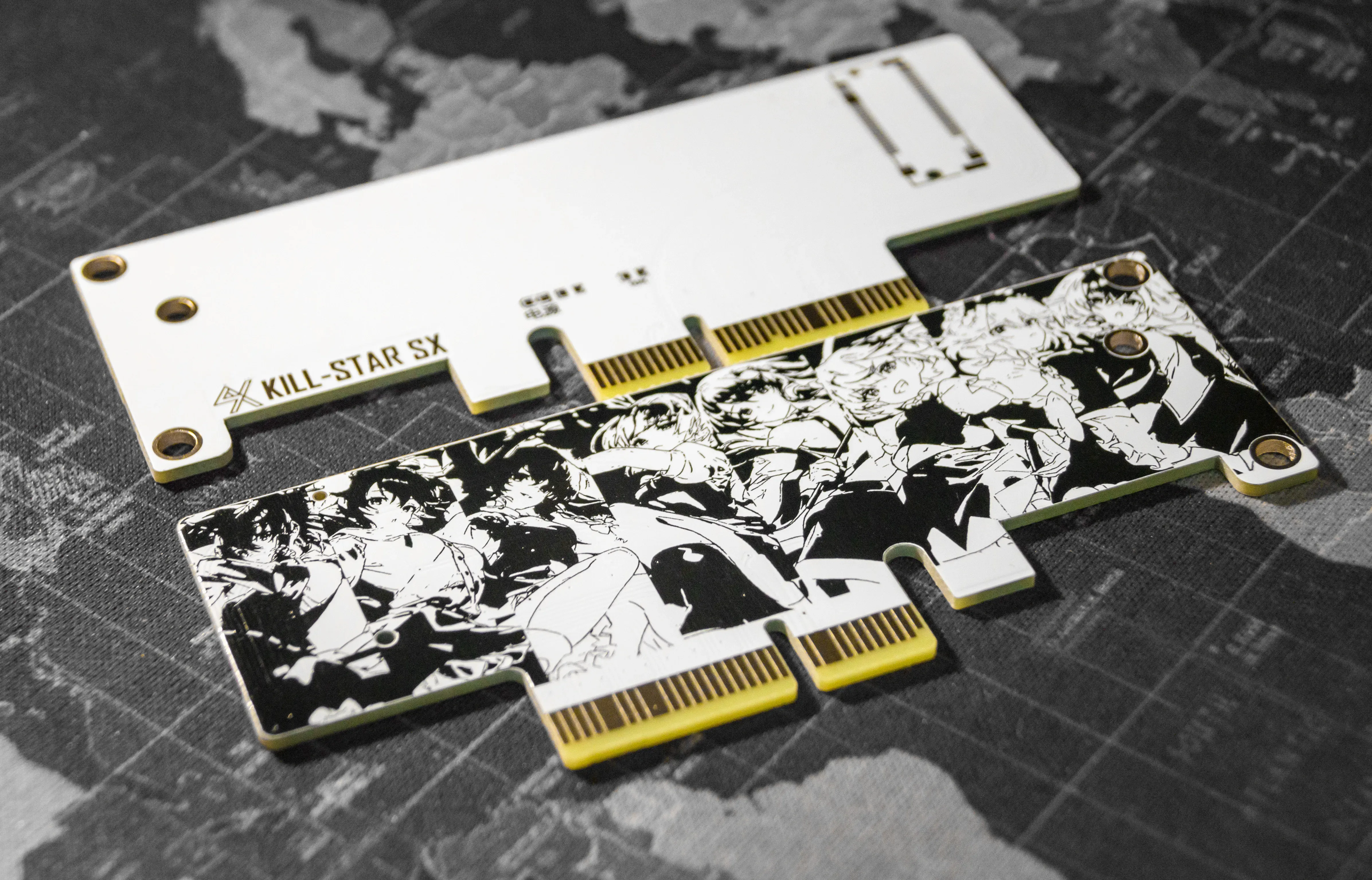
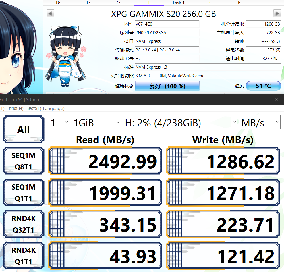
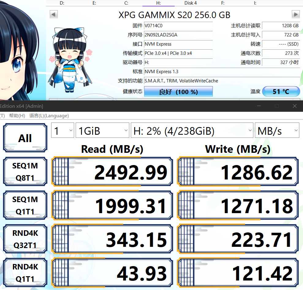
All the adapter cards have been tested and verified. Compared with the built-in interface of the motherboard, there is almost no difference in transmission rate. The PCB has both horizontal and vertical insertion versions. Two round holes on the horizontal insertion version can be used to install a cover, and it supports the NVME protocol.
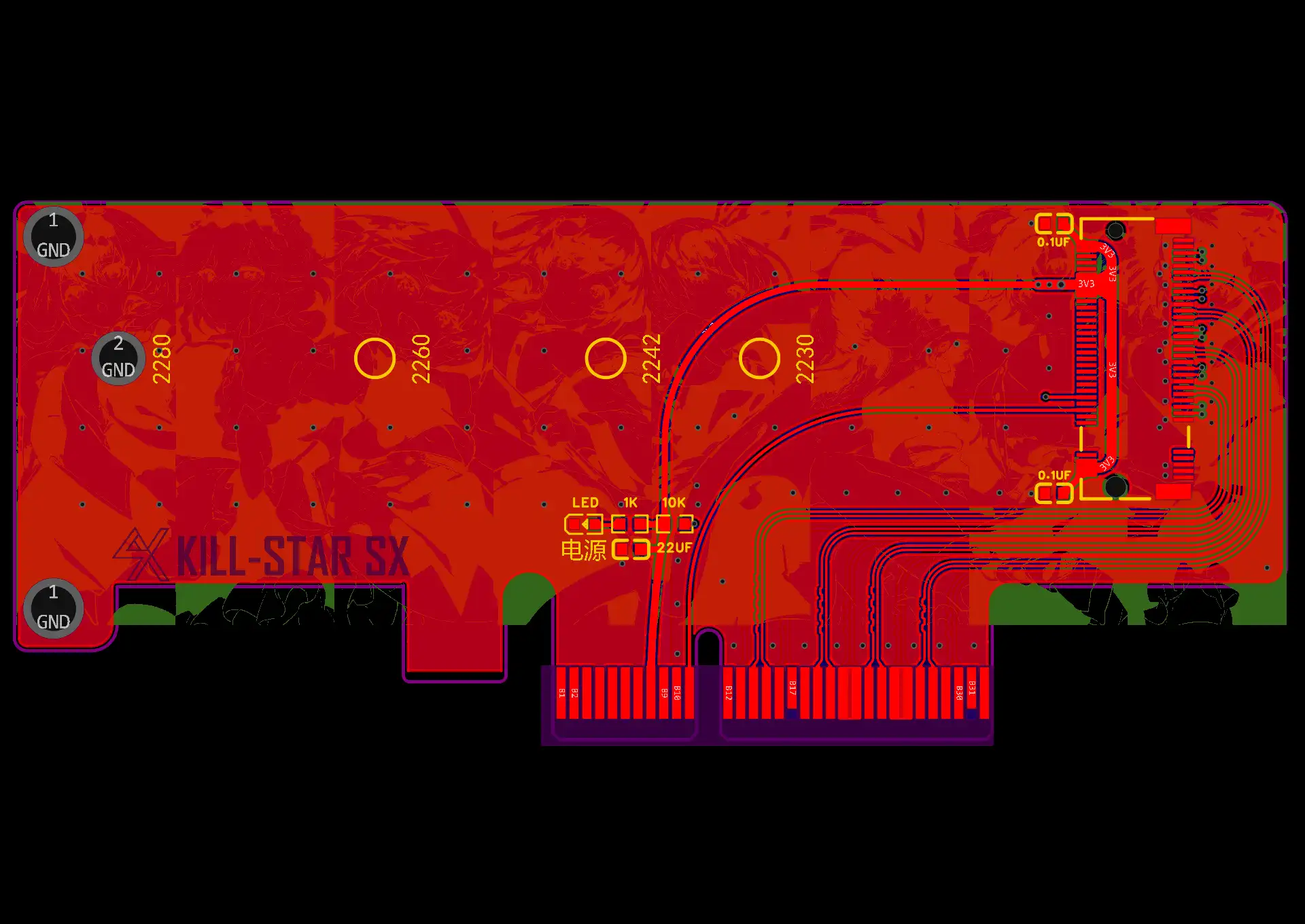
The PCB adopts differential equal-length wiring, with a designed impedance of 100 ohms. Considering the cost, it is advisable to use a double-layer board as much as possible. The copper plating range has been set, and after opening it, it may need to be re-plated (do not modify the copper plating range, otherwise it may cause incorrect copper plating, short circuits, and damage to computers and other equipment). The installation holes only support 2280 hard drives (most long M.2 solid-state drives on the market are of 2280 specification). 2230 and 2242 are two special specifications of holes that can be placed over the vias according to personal needs. The 22110 specification is not currently supported. The board thickness is 1.6. It is recommended to use gold plating first. Tin plating has been tested for more than a year and there is a probability of oxidation and discarding the disk, causing insertion and removal problems or damaging the computer and other equipment. (The test environment is a relatively humid southern area, with a self-designed open aluminum frame machine rack inside).
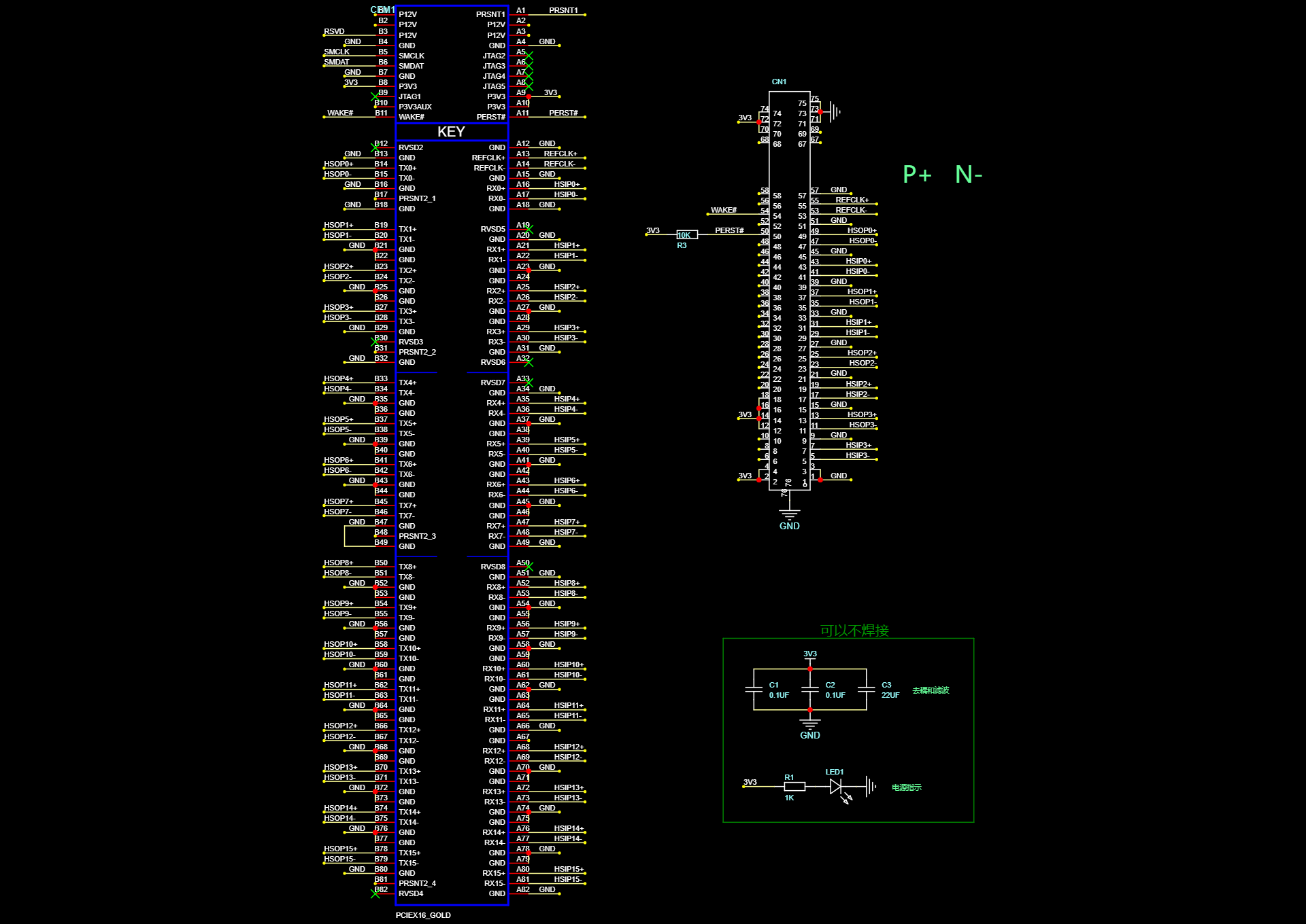
The minimum operation only requires a 10K pull-up resistor and the NGFF (M.2) interface. The power indicator light and decoupling filter capacitor can be soldered according to personal needs. Generally, a good power supply and motherboard filter are sufficient and do not need to be soldered. Brand-name power supplies are recommended to be soldered with capacitors. (After verification, it has been tested and verified by many friends that everything is normal when soldering the boards).
NGFF interface: It is highly recommended to have a height of 3.2mm. Make sure to buy M-KEY, otherwise, the M.2 hard drive cannot be connected! The NGFF (M.2) interface is difficult to solder. Many people have reported that after soldering well, the insertion does not respond, which is likely to be a short circuit or false soldering. (After verification, it has been tested and verified by many friends that everything is normal). If you are not confident in your soldering skills or are a beginner, it is recommended to go to SMT or find a good friend who is a welder to do the outsourcing.
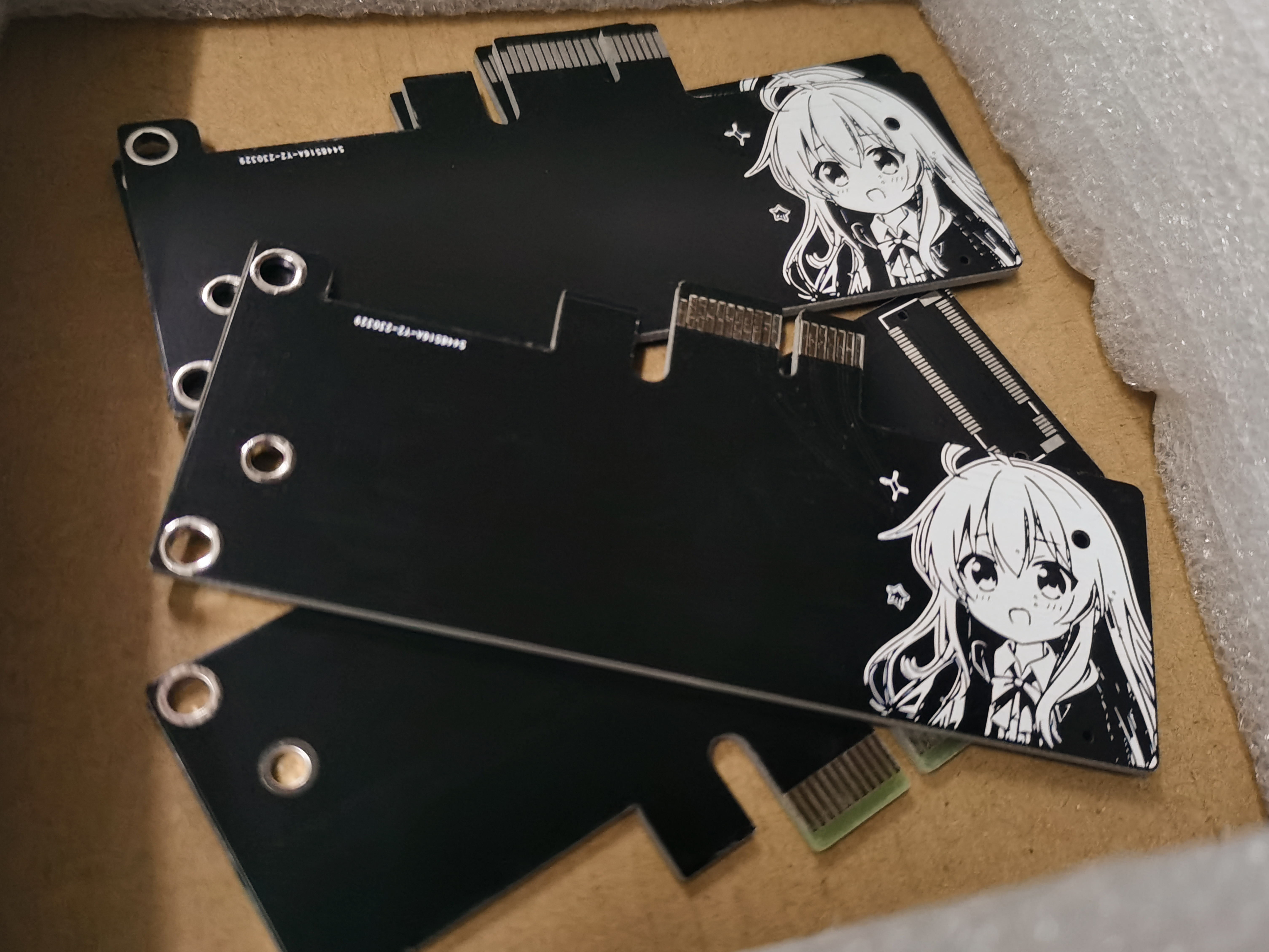
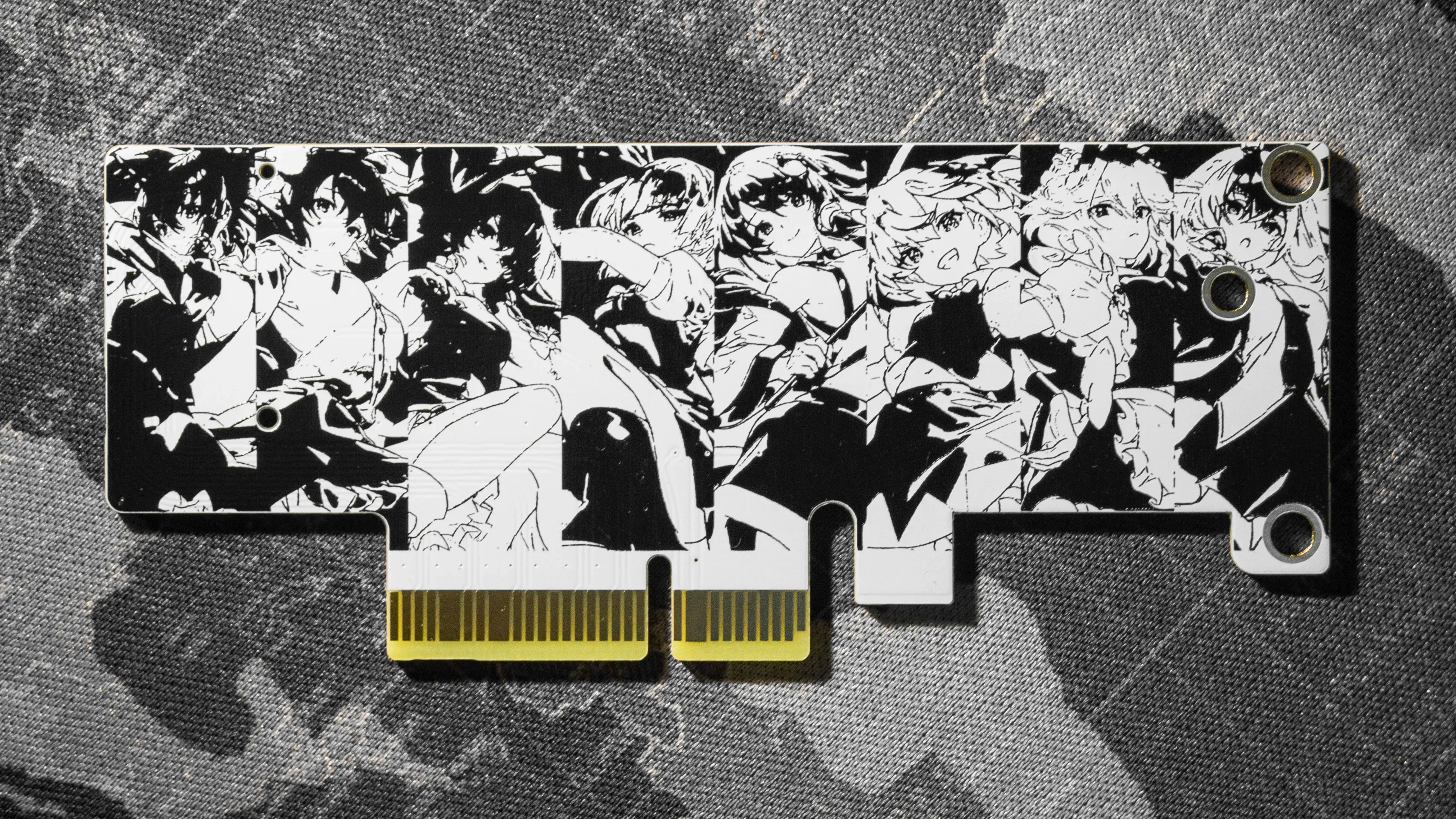
The default PCB has some patterns. It is best to use white PCB. If you don't like it, you can replace it with your own favorite pattern. The pattern should be placed on the back of the NGFF (M.2) port. Before soldering the board, check the pattern in 3D mode and then proceed with the soldering.